 |
 |
 |
 |
 |
 |
||
 |
 |
 |
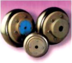
Tyre Couplings with a choice of 3 types of tyres and a range of 14 sizes from 24 to
The heart of the wiperdrive Coupling is the resilient tyre which is the result of wiperdrive Technology The specially designed reinforcement of the tyre ensures higher life, lower downtime, hence improved productivity. Tyre Couplings can absorb *Parallel misalignment upto 4 mm *Angular misalignment upto 40 *End float up to 5 mm Tyre is different. It embodies all the desirable features of an ideal flexible coupling TORSIONALLY SOFT Absorbs Shock forces MISALIGNMENT Handles combinations of parallel, Angular and axial misalignments FREE OF BACK – LASH Does not create ‘snatch’ on take-up of the drive DAMPING Reduces vibrations and torsional oscillations
|
NO RELATIVE MOVING PARS Eliminates the need for lubrication MAINTENANCE No dismantling needed for inspection of components INSTALLATION Requires no special tools SHAFT SEPARATION Quickly and easily accomplished ENVIRONMENT Use of natural or neoprene rubber Compounds make Tyre Couplings Suitable for use in most conditions. TYRE SELECTION Details required for coupling selection are (1) Tyre of driven machine and operating hours per day. (2) Speed and power absorbed by driven machine (if absorbed power is not known, calculate on power rating of prime mover) |
14,700 Nm at 1440 rpm.
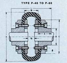
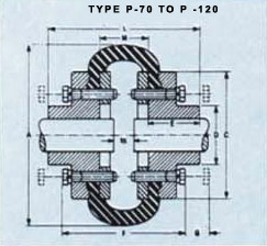
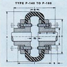
| SIZE | POWER PER 100 REV/MIN KW | MAX.SPEED REV/MIN | BORE | A mm | Lmm | Dmm | Emm | Cmm | G**mm | M+mm | Fmm | APPROX.WT.(kgs) | |
| MIN mm | MAX mm | ||||||||||||
P-40 P-45 P-50 P-60 P-70 P-80 P-85 P-90 P-100 P-110 P-120 P-140 P-160 P-180 |
0.22 0.39 0.56 1.11 1.70 2.65 3.20 3.82 5.29 7.46 12.40 19.70 21.60 57.40 |
4500 4500 4500 4000 3600 3100 3000 2880 2600 2300 2050 1800 1600 1500 |
11 11 16 16 19.05 25.4 31.75 31.75 31.75 31.75 38.1 75 75 75 |
30 32 38 48 55 65 70 76 85 90 102 120 140 150 |
104 120 133.5 165 197 211 222 235 254 279 314 359 402 470 |
67 73 92 112.4 132 150 153 164 178 180 207 204 220 258 |
- - - 73 82 95 103 110 124 134 152 195 216 266 |
22 25 32 38 45 51 53 57 60 65 76 89 102 114 |
82 94 100 125 144 167 179 188 216 233 264 313 345 395 |
43 43 43 43 10 10 13 13 13 14 14 14 19 19 |
22 24 25 33 40 43 44 46 48 44 49 24 30 46 |
- - - - 101 106 107 119 123 127 140 152 156 188 |
2.0 2.2 4.0 5.0 8.0 12.0 14.0 15.0 21.0 28.0 41.0 61.0 86.0 141.0 |
|
SHAFT ENDS ALTHOUGH NORMALLY LOCATED M APART CAN PROJECT BEYOND THE FLANGE AS SHOWN. IN THIS EVENT ,ALLOW SUFFICIENT SPACE BETWEEN SHAFT ENDS FOR THE END FLOAT AND MISALIGNMENTS TYRE COUPLING UPTO SIZE P-180 WITH QUICK FITTING TAPER LOCK SYSTEM ALSO AVAILABLE .CONSULT WIPERDRIVE |
| wiperdrive© copyright. 2002 |